Hardware Overview
Hardware Capabilities
Total Video Inputs: 2 (1 HDMI, 1 SDI) HDMI at 4kp60, SDI at 1080p60
Total Video Outputs: 3 (2 HDMI, 1 SDI) HDMI at 4kp60, SDI at 1080p60
Audio Outputs: 2 (via 1x TRS 3.5mm Jack)
Ethernet: 2x 2.5G Ethernet ports
Wifi: Intel AX210 (wifi 6E)
Total Hardware Accelerated Encoders: 8 (4 user defined, 4 SYGNAL defined).
Total Hardware Accelerated Decoders: 4
Power: Via 11-14v V Mount Supply or by 5-20V DC barrel jack. Minimum 20W supply required.
Tally: Via TRRS 3.5mm Jack on top of unit. Sleeve: Ground Tip: Red Ring 1: Green Ring 2: Blue
Dimensions: Width = Height = Depth =
Hardware Diagram
The sygnalTRX 2x3 is a 2 input, 3 output wireless network encoder/decoder with additional add-on features such as teleprompting. Below is a broad overview of the hardware.
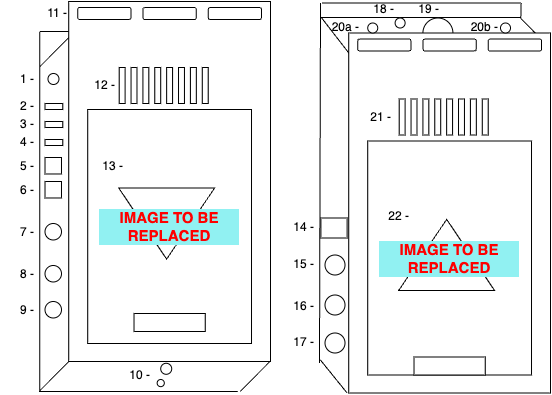
| 1 - Stereo Audio out | 2 - HDMI Out 1 | 3 - HDMI Out 2 | 4 - HDMI In | 5 - Ethernet 1 |
| 6 - Ethernet 2 | 7 - SDI IN | 8 - SDI Out | 9 - Reference In | 10 - 1/4'' and 3/8'' threads |
| 11 - Cable Tie Slots | 12 - Cooling Vents | 13 - V Mount Plate | 14 - OLED Display | 15 - Record Button |
| 16 - Identify Button | 17 - User Button | 18 - Tally TRRS Jack | 19 - Power Button | 20 - Antenna SMAs |
| 21 - Cooling Vents | 22 - V Mount Plate | TBI - DC Barrel Jack |
The OLED Display
The OLED display shows useful information such as current wifi status and strength, IP addresses of network interfaces, V Mount battery voltage and record status information such as time remaining to record. It also shows device stats such as temperature, CPU and RAM usage to allow engineers to monitor the status of the units.
The Buttons
The sygnalTRX 2x3 has three large buttons on the left hand side which allow for quick operation of commonly needed functions without having to use the web GUI or sygnalCONTROL.
No Comments