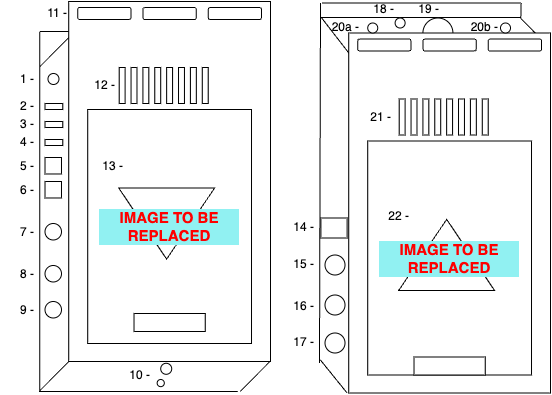
# SYGNALcam # Unit Overview This is an overview of the hardware and broad capabilities of the sygnalTRX unit. # Hardware Overview #### Hardware Capabilities Total Video Inputs: 2 (1 HDMI, 1 SDI) HDMI at 4kp60, SDI at 1080p60 Total Video Outputs: 3 (2 HDMI, 1 SDI) HDMI at 4kp60, SDI at 1080p60 Audio Outputs: 2 (via 1x TRS 3.5mm Jack) Ethernet: 2x 2.5G Ethernet ports Wifi: Intel AX210 (wifi 6E) Total Hardware Accelerated Encoders: 8 (4 user defined, 4 SYGNAL defined). Total Hardware Accelerated Decoders: 4 Power: Via 11-14v V Mount Supply or by 5-20V DC barrel jack. Minimum 20W supply required. Tally: Via TRRS 3.5mm Jack on top of unit. *Sleeve: Ground Tip: Red Ring 1: Green Ring 2: Blue* **Dimensions: Width = Height = Depth =** #### Hardware Diagram The **sygnalTRX 2x3** is a 2 input, 3 output wireless network encoder/decoder with additional add-on features such as teleprompting. Below is a broad overview of the hardware.
1 - Stereo Audio out2 - HDMI Out 13 - HDMI Out 24 - HDMI In5 - Ethernet 1
6 - Ethernet 27 - SDI IN8 - SDI Out9 - Reference In10 - 1/4'' and 3/8'' threads
11 - Cable Tie Slots12 - Cooling Vents13 - V Mount Plate14 - OLED Display15 - Record Button
16 - Identify Button17 - User Button18 - Tally TRRS Jack19 - Power Button20 - Antenna SMAs
21 - Cooling Vents22 - V Mount Plate**TBI - DC Barrel Jack**
#### The OLED Display The OLED display shows useful information such as current wifi status and strength, IP addresses of network interfaces, V Mount battery voltage and record status information such as time remaining to record. It also shows device stats such as temperature, CPU and RAM usage to allow engineers to monitor the status of the units. #### The Buttons The sygnalTRX 2x3 has three large buttons on the left hand side which allow for quick operation of commonly needed functions without having to use the [web GUI](https://wiki.sygnal.tv/books/sygnalcam/page/accessing-the-sygnaltrx-web-gui "Accessing the sygnalTX GUI") or sygnalCONTROL. The first button is record. When pressed, it will illuminate and pulse red, indicating that the unit is now recording. The OLED display will show the current filename and the remaining record time on disk. The second button is identify. When short - pressed, the unit's buttons will do a "chase" indicating that the identify function is running. Simultaneously, all instances of this unit's web GUI will flash brightly, and the unit will move to the top of the device list in sygnalCONTROL and flash, making it clear which unit is being identified. When long-pressed (button held for longer than 5 seconds), the device will enter Access Point mode. This will allow an engineer to connect to the device directly via its own wifi network, enabling them to do first time configuration such as set the SSID and password. The third button is a user-defined button. The function of this button can be defined in the GUI's [SYSTEM](https://wiki.sygnal.tv/books/sygnalcam/chapter/system "System") page, or in sygnalCONTROL. Functions include starting/stopping a particular stream, blanking the teleprompter, rotating an output and more. # Getting Started # First Time Network Connection ### Connecting to your sygnalTRX unit for the first time. First, you must connect to your unit via a network connection. There are multiple ways to connect to your sygnalTRX unit to a network. Below is a list of these methods, which are explored in more detail below. The variety of options is there to ensure that no matter the scale of your system, there is always a quick and convenient way to set up your sygnalTRX units for the first time. 1 - Plug unit into an existing network which has a DHCP server. 2 - Plug unit into an existing network without DHCP. 3 - Plug unit directly into your computer via its network connection. 4 - Use Access point mode to connect to the device directly over wifi, enabling you to configure the sygnalTRX unit to connect to an existing WIFI network. 5 - Use a USB stick to flash a configuration file to the unit (including network connection information), enabling rapid programming of multiple sygnalTRX units. #### 1 - Connecting the unit to an existing network which has a DHCP server. Plug your sygnalTRX unit into your network using a cat5e cable (or above). Wait for it to be given an IP address (usually about 10 seconds). As soon as this happens, the IP address will be displayed on the OLED display. At this point, you can connect to the device via its web GUI, or via the sygnalCONTROL app. To access the web GUI, ensuring that your computer is on the same network and subnet (or has routes to), enter the IP address in your web browser to access the sygnalTRX GUI. To connect via the sygnalCONTROL app, ensuring that your computer is on the same subnet, click the + icon in the bottom left of the screen. Now select the discovered device from the list and press "add". Alternatively, you can type in the IP address for the sygnalTRX unit if it is on a different subnet which will means the automatic discovery will not work. #### 2- Plug unit into an existing network without DHCP. Plug your sygnalTRX unit into your network using a cat5e cable (or above). Wait for it to be given an automatically assigned IP address (usually about 10-20 seconds). As soon as this happens, the IP address will be displayed on the OLED display. At this point, you can connect to the device via its web GUI, or via the sygnalCONTROL app. To access the web GUI, ensuring that your computer is on the same network and subnet (or has routes to), enter the IP address in your web browser to access the sygnalTRX GUI. To connect via the sygnalCONTROL app, ensuring that your computer is on the same subnet, click the + icon in the bottom left of the screen. Now select the discovered device from the list and press "add". Alternatively, you can type in the IP address for the sygnalTRX unit if it is on a different subnet which will means the automatic discovery will not work. #### 3 - Plug unit directly into your computer via its network connection. Plug your sygnalTRX unit into your computer using a cat5e cable (or above). Wait for it to be given an automatically assigned IP address (usually about 10-20 seconds). As soon as this happens, the IP address will be displayed on the OLED display. At this point, you can connect to the device via its web GUI, or via the sygnalCONTROL app. To access the web GUI, ensuring that your computer is on the same network and subnet (or has routes to), enter the IP address in your web browser to access the sygnalTRX GUI. To connect via the sygnalCONTROL app, ensuring that your computer is on the same subnet, click the + icon in the bottom left of the screen. Now select the discovered device from the list and press "add". Alternatively, you can type in the IP address for the sygnalTRX unit if it is on a different subnet which will means the automatic discovery will not work. #### 4 - Use Access point mode to connect to the device directly over wifi, enabling you to configure the sygnalTRX unit to connect to an existing WIFI network. Press and hold the "ID" button on the left hand side of the unit until it starts flashing (5 seconds). On your computer/phone/laptop, connect to the wifi network it has just created. The SSID will be its serial number (printed on the base of the unit). The password will be be the same as the SSID: its serial number. This should open a captive portal which displays the web GUI. If it doesn't, visit the IP address shown on the OLED screen on side of the sygnalTRX unit. Configure the device how you wish, for example by adding the SSID and password for your wifi network. To take the device out of access point mode, press the flashing ID button once more. The device will now try and connect to the new network you added. #### 5 - Use a USB stick to flash a configuration file to the unit (including network connection information), enabling rapid programming of multiple sygnalTRX units. Open sygnalCONTROL. To do this, visit the IP address of a sygnalCORE or sygnalGLUE server already on your network, or download the sygnalCONTROL standalone app on your computer by visiting [https://sygnal.tv/control](https://sygnal.tv/control) At the bottom left of the screen, click the '+' icon to add a device, and select virtual device. Select your model of sygnalTRX unit, and then click "add". Ensuring you're on the "device" view tab of sygnalCONTROL, select the virtual device you just made from the list on the left. On the right hand side of the screen you can create a configuration for the device you wish to add. For more details on using sygnalCONTROL, please see the [sygnalCONTROL manual.](https://wiki.sygnal.tv/books/sygnalcontrol "sygnalCONTROL") Once you have finished creating the configuration, click the "download config" button and save it to the root directory of a FAT32 formatted USB drive. Safely eject the drive, then plug it into the SYGNAL unit you wish to flash with this configuration. All three buttons will flash once the flash has completed succesfully. You may now remove the USB stick. The unit will now connect to whatever wifi network you configured, and you'll be able to access its GUI by visiting the IP address displayed on the OLED display, or alternatively you may add it to SYGNAL control via its auto discovery or by typing in this IP address. # Accessing the sygnalTRX Web GUI Once your sygnalTRX unit is [connected to the network](https://wiki.sygnal.tv/books/sygnalcam/page/first-time-network-connection "First Time Network Connection"), the GUI can be accessed simply by going to the IP address of the device in a web browser. This is displayed on the OLED display on the side of the device. If your device has multiple IP addresses, for example because it is connected both via WIFI and also by ethernet, both IP addresses will be shown in a scrolling list. Chromium based browsers (e.g. Google Chrome) are preferred to ensure that all features work perfectly as tested. Mozilla Firefox also works, but with minor UI bugs such as requiring a page refresh to reconnect to a device after it is rebooted. # Adding a sygnalTRX unit to the device list in sygnalCONTROL. If you wish to administer your device via sygnalCONTROL, rather than directly via the web GUI, first open sygnalCONTROL. This can be achieved by visiting the IP address of a sygnalCORE or sygnalGLUE server, or by downloading and installing the standalone sygnalCONTROL app from [https://sygnal.tv/control](https://sygnal.tv/control) . To add a new device to the device list in sygnalCONTROL, ensure that you are in the "Device" tab, then click the '+' icon in the bottom left of the screen, at the bottom of the device list. Select 'Sygnal Device' from the list, and then either select 'add' next to the auto discovered sygnalTRX unit, or manually type in the IP address of your sygnalTRX unit. Auto discovery does not work across subnets as it is using bonjour. Once added, your sygnalTRX unit can be administered by selecting it from the device list, then configuring it in the configuration pane on the right of the screen. # The sygnalTRX web GUI # Network ### The network configuration tab The network configuration tab is split into two halves: Wifi, and everything else. #### On the left To connect to a discovered SSID, click the connect button and then fill out the authentication details. If successful, the sygnalTRX unit will connect to the new wifi network. To delete a saved SSID, press the "forget" button next to it. For networks not currently discovered, scroll to the bottom of the list, where you will find all saved networks. To manually add an SSID which is not currently discoverable, press "add manually". Fill out the SSID and authentication details and then press save. The sygnalTRX unit will try to connect to this, and if it fails it will try again if this SSID comes in range. The list of discovered network devices refreshes once when you open the network tab. To manually refresh the list, press the refresh button. The list does not scan continuously to prevent negatively impacting the performance of network roams. #### On the right To configure your wired network settings, and (for 5G variants) the 5G interface settings, find the adapter settings on the right hand side of the page. By default, each adapter will behave as a DHCP client. To manually configure network settings, disable DHCP using the toggle button and then fill in fields such as IP address, netmask, gateway and DNS and click update. Tooltips to the right of each field contain more information that should help you if you're stuck. Each device can be enabled and disabled using the thus labelled toggle switch. The 'add to bridge' adds the interface to an internal network bridge. This can be useful if - for example - you wish give wireless network to a camera that does not have wifi, and instead only wired network. Simply bridge the WIFI and ethernet ports on the sygnal unit, then plug the a cable between the ethernet port and the camera. Selecting "hotspot mode" on the wifi adapter will act in the same way as pressing and holding the ['ID' button](https://wiki.sygnal.tv/books/sygnalcam/page/hardware-overview "Hardware Overview") on the side of the sygnalTRX. The unit will disconnect from its current wifi network (if it is currently connected), and produce its own network with an SSID matching the unit's serial number, which can be found on the base of the unit. The password will also be the unit's serial number. # Encoders The encoders tab is where you go to take an input, encode it and stream it somewhere. The sygnalTRX 2x3 has 8 on board hardware encoders (at 1080p60). 4 of these hardware encoders available to the user. Each of these encoders also generates a low resolution sub-encode which is available as a webRTC source for the Sygnal system to use for things such as multi viewers and iPad camera multiviews. The encoders tab is split into three columns: Source, Encoder, Stream. If you have not yet created an encoder, click on the "add hardware encoder" button, then select your chosen codec. This will create a new row with a source, encoder and stream. ### Source In this column, the user choses from the list of available sources to feed into the encoder. The options are: SDI input 1 HDMI input 1 Prompter Moudle Out Playback Module Out Bars Generator No Source Select one of these from the dropdown list, and click 'set'. Changing the source will - obviously - interrupt the streams. So don't do this while on air! In the top right corner of the stream block is an 'x' which sets the source back to 'No Source'. Next to this there is a restart button which restarts the input, which can be useful for giving the system a "kick" in the unlikely event that the source changes format and the sygnalTRX does not detect this change automatically. In the body of the stream block, useful information is displayed such as the format and frame rate. In the top left corner of the stream block is a status light. Green means a valid signal is present. Red means there is no valid signal present. ### Encoder In this column you can configure the encoder profile. Select the cog in the top right corner of the encoder to change these settings. There are tooltips which describe each parameter in detail. For further details, tooltips contain links to the glossary of terms. LUTS can also be applied here. Simply upload the .cube file in browser, or browse from our selection of pre-installed LUT files. Once you are happy with your changes, press 'set'. Or if unhappy, press 'cancel' to cancel. Changing some parameters in the encoder will cause the stream to stop and restart, dropping a frame or more. If this is the case, a message will alert you to this next to the set button. If you are happy with your parameters and wish to save them as a default, press the "save" button next to the preset dropdown, and give it a name when prompted. If you wish to copy the settings to quickly apply them to another encoder, press the "copy" button and then the "paste" on the destination encoder. In the top center of the encoder block, there is a toggle switch to enable and disable the encoder. In the top right of the encoder block, there is a restart button: to restart the encoder; a cog: to configure the encoder; and an 'x' which deletes the encoder. In the body of the encoder block, useful information is displayed such as the codec, format, frame rate and which LUT is currently applied. In the top left of the encoder block is a status light. Green means that the encoder is running and encoding successfully. Red means that the encoder is not currently running and encoding successfully. ### Stream In the streams column, you can add, manage and delete streaming destinations. To add a stream, click add, and then configure the streaming destination. There is a field for entering a human readable name like "Jamie's Facebook Live", so that you can easily keep track of which stream is which. To delete a stream, click the 'x' icon at the top right of a streaming block. To edit a stream, click the cog icon at the top right of a streaming block. If you are happy with your parameters and wish to save them as a default, press the "save" button next to the preset dropdown, and give it a name when prompted. If you wish to copy the settings to quickly apply them to another encoder, press the "copy" button and then the "paste" on the destination stream. In the top center of the streaming block there is a toggle switch to turn a streaming destination on or off. In the top left of the streaming block is a status light. Green means it is successfully streaming to its destination. Red means it is not successfully streaming. ### Assigning the user button to a function Some functions, such as enabling and disabling a stream can be assigned to the [SYGNAL user button](https://wiki.sygnal.tv/books/sygnalcam/page/hardware-overview "Hardware Overview") on the side of the device. To quickly add a function to the user button, click the sygnal logo icon next to that button, and click "yes" when it asks if you wish to add that function to the user button. To remove the function, click the sygnal logo icon again. A list of functions that the user button is currently configured to perform can be found in the [system page](https://wiki.sygnal.tv/books/sygnalcam/page/system "System"). # Outputs There are 5 routable destinations in the "Outputs" tab. First there are the 3 hardware outputs: HDMI 1, HDMI 2 and SDI. Next is the input to the record/playback module, and lastly there is the "return" input to the Prompt module. By default, bars is routed to all outputs. This enables you to find out information about your sygnalTRX unit such as IP address and serial number simply by plugging a screen in. ### Routing to an output The page is split into two columns, with the destination fixed on the right and the source as a dropdown on the left. To create an output, select a destination from the dropdown list in the bottom middle of the screen and click "set". This will create a new output row. To patch something to the output, select a source from its corresponding dropdown list and then click "set". If you selected a streaming source, you can edit its details by clicking the cog icon in the top right corner of the source block. You can use the on/off toggle in the top center of the block to turn a destination on and off. To change a destination, you can select another from the dropdown list in the destination block and click "set". Useful information, such as the format and frame rate is displayed in both the source and destination blocks. Clicking the 'x' at the top corner of the destination block will remove that destination row. # Prompt The sygnalPROMPTER is a licensable add-on available for all sygnal units. The prompter output is generated on device which means that there is no encoding/decoding latency, allowing for super low latency prompting and smooth scrolling. ### Licensing the prompter Licenses are sold as time restricted, or perpetual. Licenses can be purchased via a syngalTRX's web GUI [System page](https://wiki.sygnal.tv/books/sygnalcam/page/system "System") if the unit has an internet connection, or from [https://sygnal.tv/licenses](https://sygnal.tv/licenses) . Licenses purchased via the website can be installed by copy and pasting or uploading the license key file into the web GUI on the [System page](https://wiki.sygnal.tv/books/sygnalcam/page/system "System"). Once licensed, the prompter can be edited and controlled via the unit's GUI at http://<device ip address>/prompt or via the desktop sygnalPROMPT application, available for Mac, Windows and Linux at [https://sygnal.tv/prompt](https://sygnal.tv/prompt). ### Using the prompter via the web GUI Visit the web GUI for your sygnalTRX unit. Go to the 'Prompt' tab. Here you will find a basic web-based text editor and prompt controls which will allow you to control the teleprompter output of this device. ### Using the prompter via the sygnalPROMPTER application Download the latest version of sygnalPROMPT at [https://sygnal.tv/prompt](https://sygnal.tv/prompt) Click the device manager tab, and then click the '+' icon to add the chosen sygnalTRX unit. If on the same subnet, it will be auto discovered. If not, you can add it using the device's IP address. Once the device is added to the list, check the "prompting" box next to it, such that your open prompting session begins transmitting data to the sygnalTRX unit. For more information about the sygnalPROMPT application, please read the [sygnalPROMPTER product manual](https://wiki.sygnal.tv/books/syngalprompter "sygnalPROMPTER"). # Playback The playback module is a simple clip recorder and playback system, with network management features. It can be controlled via the sygnalTRX device's GUI, or the sygnalCONTROL application. # System The system tab is home to information about the unit, and general configuration items that were not relevant to the other tabs. ### System Information In the system information block, you will find hardware status information such as temperature, CPU usage and disk usage. You can configure the clock and timezone by clicking the corresponding "change" button next to them. At the bottom of the block are buttons which enable you to restart the software or hardware, shutdown the hardware, Identify the unit and download log files. Pressing identify will cause the sygnalTRX unit's three button LEDs to perform a "chase", clearly identifying the unit. ### Other Sygnal Units In the Other Sygnal Units block, a list of auto-discovered devices will appear. This works using bonjour, so will only automatically discover devices which are on the same subnet. There will be a quick link to access the web GUI for each of these, allowing you to quickly administer all Sygnal units on your network without necessarily knowing the IP address for all of them. ### Licenses The licenses block shows which licenses are currently active on this sygnal unit. License files can be uploaded using the upload button, or the key can be copy and pasted in. If you wish to buy a license for a currently unlicensed feature, you can click the corresponding buy button which will take you to the corresponding page in the Sygnal online shop, allowing quick and easy licensing of additional features such as the teleprompter. ### Bars Generator Here you can configure the bars generator. You can select from different test patterns, toggle the display of different unit information, set audio tone frequency and loudness. With the advanced bars license active, you can add custom text fields, company logos and play sync flashes. ### Config In the config page you can configure the sygnalTRX device's human readable name, change the login username and password as well as other more advance settings such as changing the port the web GUI uses. Here you can also test the tally output and set the logging level. At the bottom of the config block are buttons to download the current configuration state of your unit. It is split into "flows", which is your encoder and output settings. "Bars", which is your custom bars configuration, and "Network" which is your network settings. When pressing a download button, a popup will ask you to apply any filters to the download, or you can select "all". In the case of the network settings, you can enable an auto-increment function for the IP addresses, where - when using the config to flash devices via USB - the IP address will automatically increment by one after each successful flash, allowing the quick configuration of multiple devices with unique manual IP addresses. You can upload any of these configuration files by pressing the "upload button", which will apply them to the unit.